Friday, March 30, 2018

The Radiation Dose from Radon: A Back-of-the-Envelope Estimation

Intermediate Physics for Medicine and Biology: The Radiation Dose from Radon I like Fermi problems: those back-of-the-envelope order-of-magnitude estimates that don’t aim for accuracy, but highlight underlying principles. I also enjoy devising new homework exercises for the readers of this blog. Finally, I am fascinated by radon, that radioactive gas that contributes so much to the natural background radiation. Ergo, I decided to write a new homework problem about estimating the radiation dose from breathing radon.

What a mistake. The behavior of radon is complex, and the literature is complicated and confusing. Part of me regrets starting down this path. But rather than give up, I plan to forge ahead and to drag you—dear reader—along with me.
Section 17.12
Problem 57 1/2. Estimate the annual effective dose (in Sv yr-1) if the air contains a trace of radon. Use the data in Fig. 17.27, and assume the concentration of radon corresponds to an activity of 150 Bq m-3, which is the action level at which the Environmental Protection Agency suggests you start to take precautions. Make reasonable guesses for any parameters your need.
Here is my solution (stop reading now if you first want to solve the problem yourself). In order to be accessible to a wide audience, I avoid jargon and unfamiliar units.
One bequerel is a decay per second, and a cubic meter is 1000 liters, so we start with 0.15 decays per second per liter. The volume of air in your lungs is about 6 liters, implying that approximately one atom of radon decays in your lungs every second.

Radon decays by emitting an alpha particle. You don’t, however, get just one. Radon-222 (the most common isotope of radon) alpha-decays to polonium-218, which alpha-decays to lead-214, which beta-decays twice to polonium-214, which alpha-decays to lead-210 (see Fig 17.27 in Intermediate Physics for Medicine and Biology). The half-life of lead-210 is so long (22 years) that we can treat it as stable. Each decay of radon therefore results in three alpha particles. An alpha particle is ejected with an energy of about 6 MeV. Therefore, roughly 18 MeV is deposited into your lungs each second. If we convert to SI units (1 MeV = 1.6 × 10⁻¹³ joule), we get about 3 × 10-12 joules per second.

Absorbed dose is expressed in grays, and one gray is a joule per kilogram. The mass of the lungs is about 1 kilogram. So, the dose rate for the lungs is 3 × 10-12 grays per second. To find the annual dose, multiply this dose rate by one year, or 3.2 × 10⁷ seconds. The result is about 10-4 gray, or a tenth of a milligray per year.

If you want the equivalent dose in sieverts, multiply the absorbed dose in grays by 20, which is the radiation weighting factor for alpha particles. To get the effective dose, multiply by the tissue weighting factor for the lungs, 0.12. The final result is 0.24 mSv per year.
This all seems nice and logical, except the result is a factor of ten too low! It is probably even worse than that, because my initial radon concentration was higher than average and in Table 16.6 of IPMB Russ Hobbie and I report a value of 2.28 mSv for the average annual effective dose. My calculation here is an estimate, so I don’t expect the answer to be exact. But when I saw such a low value I was worried and started to read some of the literature about radon dose calculations. Here is what I learned:
  1. The distribution of radon progeny (such as 214Po) is complicated. These short-lived isotopes are charged and behave differently than an unreactive noble gas like radon. They stick to particles in the air. Your dose depends on how dusty the air is.
  2. How these particles interact with our lungs is even more difficult to understand. Some large particles are filtered out by the upper respiratory track
  3. The range of a 6-MeV alpha particle is only about 50 microns, so some of the energy is deposited harmlessly into the gooey mucus layer lining the airways (see https://www.ncbi.nlm.nih.gov/books/NBK234233). Ironically, if you get bronchitis your mucus layer thickens, protecting you from radon-induced lung cancer.  
  4. The progeny and their dust particles stick to the bronchi walls like flies to flypaper, increasing their concentration.
  5. Filtering out dust and secreting a mucus layer reduces the dose to the lungs, while attaching the progeny to the airway lining increases it. My impression from the literature is that the flypaper effect dominants, and explains why my estimate is so low.
  6. The uranium-238 decay chain shown in Fig. 17.27 is the source of radon-222, but other isotopes arise from other decay chains. The thorium-232 decay chain leads to radon-220, called thoron, which also contributes to the dose.
  7. I am not confident about my value for the mass. The lungs are a bloody organ; about half of their mass is blood. I don’t know whether or not the blood is included in the reported 1 kg mass. The radon literature is oddly silent about the lung mass, and I don’t know how these authors calculate the dose without it. 
  8. I ignored the energy released when progeny beta-decay, which would cause a significant error if my aim was to calculate the absorbed dose in grays. But if I want the effective dose in sieverts I should be alright, because the radiation weighting factor for electrons is 1 compared to 20 for alpha particles. 
  9. The radon literature is difficult to follow in part because of strange units, such as picocuries per liter and working level months (see https://www.ncbi.nlm.nih.gov/books/NBK234224).
  10. Radon can get into the water as well as the air. If you drink the water, your stomach gets a dose. With a half-life of days, the radon in this elixir has time to enter your blood and irradiate your entire body.
  11. Does the dose from radon lead to lung cancer? That depends on the accuracy of the linear no-threshold model. If there is a threshold, then such a small dose may not represent a risk.
  12. If you want to learn more about radon, read NCRP Report 160, ICRP Publication 103, or BEIR VI. Of course, you should start by reading Section 17.12 in IPMB.
What do I take away from this estimation exercise? First, radon dosimetry is complicated. Second, biology problems are messy, and while order-of-magnitude estimates are still valuable, your results need large error bars.

Friday, March 23, 2018

95gTc and 96gTc as Alternatives to Medical Radioisotope 99mTc

Intermediate Physics for Medicine and Biology: 95gTc and 96gTc as Alternatives to Medical Radioisotope 99mTc In Chapter 17 of Intermediate Physics for Medicine and Biology, Russ Hobbie and I discuss the most widely used radioisotope in nuclear medicine: 99mTc (technetium-99m). Previously in this blog (here, here, and here) I described the looming shortage of 99mTc. In a recent paper in the open access journal Heliyon (Volume 4, Article Number e00497, 2018), Hayakawa et al. review “95gTc and 96gTc as alternatives to medical radioisotope 99mTc.” I don’t know enough nuclear medicine to judge if 95gTc and 96gTc are realistic alternatives to 99mTc, but the idea is intriguing. Below I reproduce an abridged and annotated version of the introduction to this interesting paper (my comments are in italics and enclosed in brackets []). Enjoy!
Various radioisotopes, such as 99mTc (half-life 6.02 h [hours]), 201Tl [thallium-201] (half-life 3.04 d [days]), and 133Xe [xenon-133] (half-life 5.27 d), are used for single-photon emission computed tomography (SPECT) in medical diagnostic scans. In particular, 99mTc has become the most important medical radioisotope at present… Over 30 commonly used radiopharmaceuticals are based on 99mTc [for example, 99mTc–sestamibi, 99mTc–tetrofosmin, and 99mTc-exametazime]... The 99mTc radioisotopes are supplied by 99Mo/99mTc generators, which continuously generate 99mTc through the β-decay of the parent nucleus 99Mo [molybdenum-99 is trapped in alumina (Al2O3) where it decays to pertechnetate (TcO4-); eluting solution flowing through the alumina collects the 99mTc]... This supply method provides two excellent advantages. First, it is possible to transport 99Mo/99mTc generators from a production facility to any place in the world because the half-life of 99Mo is... 2.75 d. Second, when a 99Mo/99mTc generator is transported to a hospital, 99mTc can be produced fresh for up to 2 weeks by daily milking/elution from this 99Mo/99mTc generator. At present, the parent nucleus 99Mo is produced in nuclear reactors by the neutron-induced fission of 235U [uranium-235] in highly enriched uranium (HEU) targets, in which the fraction of 235U is approximately 90%. However, some nuclear reactors that have supplied 99Mo require major repairs or shutdown [for example, the Chalk River reactor in Ontario, Canada], which may lead to a 99mTc shortage. Thus, many alternative methods to produce 99Mo or 99mTc [such as in a cyclotron] without HEU have been proposed…
The September 11th terrorist attacks in Washington D.C. [these attacks actually took place in New York City, at the Pentagon in Arlington County Virginia, and near Shanksville, Pennsylvania] in 2001 also affected medical radioisotope production from the viewpoint of the safeguards of nuclear materials. The control of fissionable nuclides such as 235U and 239Pu [plutonium-239] is important for the safeguards of nuclear materials… The International Atomic Energy Agency (IAEA) hopes to discontinue 99mTc production using HEU targets, which can be transmuted into nuclear weapons... In the near future, 99mTc will be supplied by nuclear reactors using LEU [low-enriched uranium] targets in addition to HEU. The Nuclear Energy Agency (NEA) reported the prediction that the 99Mo/99mTc supply will be larger than the world demand when the scheduled nuclear reactors using LEU start 99Mo production…

Because the Tc [technitium] chemistry is the same, all the radiopharmaceuticals based on 99mTc can, in principle, be applied to other Tc isotopes. There are five Tc isotopes with half-lives in the range from hours to days: 94mTc (half-life 52 m [minutes]), 94gTc (half-life 4.88 h), 95mTc (half-life 60 d), 95gTc (half-life 20 h), and 96gTc (half-life 4.28 d) [superscript “g” stands for ground state, whereas superscript “m” stands for metastable excited state]… The half-life of 96gTc (4.28 d) is long enough for worldwide delivery from a production facility and lengthy use of up to 2 weeks in hospitals. 95gTc (20 h) can also be transported to a wide area and used for 3–5 days in hospitals. Thus, 95gTc and 96gTc are candidates for alternative γ-ray emitters. However, the decay rates of 95gTc and 96gTc are lower than that of 99mTc by a factor of 3.3 and 17, respectively, because the decay rate of a radioisotope is inversely proportional to its half-life. This fact leads to the question of whether these isotopes can work as 99mTc medical radioisotopes.

In the current study, we present the relative γ-ray flux of these isotopes with simple assumptions. We also estimate the patient radiation does [dose] per Tc-labeled tracer using… PHITS [Particle and Heavy Ion Transport code System, a general purpose Monte Carlo particle transport simulation code]... Various nuclear reactions that are production methods of Tc isotopes, such as (p, n) reactions [in which a proton enters the nucleus and a neutron leaves it]…, deuteron [hydrogen-2]-induced reactions…, and 96Ru [ruthenium-96] (n, p)96gTc reactions…, were studied. We consider the production by the (p, n) reaction on an enriched Mo isotope. We also calculate the production rate using a typical PET [positron emission tomography] medical cyclotron [If you must make 96gTc in a cyclotron, why not make 99mTc in the cyclotron instead?]. Because the energies of decay γ-rays of these Tc isotopes are typically higher than 200 keV, they are not suitable for the traditional SPECT cameras. Thus, we also discuss the property of possible ETCC [Electron-Tracking Compton Camera] for high energy γ-rays.

Friday, March 16, 2018

Another Analytical Example of Filtered Back Projection

Intermediate Physics for Medicine and Biology: Another Analytical Example of Filtered Back Projection Some people collect stamps, aged bottles of wine, or fine art. I collect analytical examples of tomographic reconstruction: determining a function f(x,y) from its projections F(θ,x'). Today Ill share my latest acquisition: an example of filtered back projection. I discussed a similar example in a previous post, but you cant have too many of these. This analysis illustrates the process that Russ Hobbie and I describe in Section 12.5 of Intermediate Physics for Medicine and Biology.

The method has two steps: filtering the projection (that is, taking its Fourier transform, multiplying by a filter function, and doing an inverse Fourier transform) and then back projecting. We start with a projection F(θ,x'), which in the clinic would be the output of your tomography machine.
The projection used in an analytical example of filtered back projection.
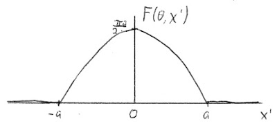
This projection is independent of the angle θ, implying that the function f(x,y) looks the same in all directions. A plot of F(θ,x') as a function of x' is shown below.
A plot of the projection used in an analytical example of filtered back projection.
I suggest you pause for a minute and guess f(x,y) (after all, our goal is to build intuition). Once you make your guess, continue reading.


Step 1a: Fourier transform

The Fourier transform of the projection F(θ,x') is
The Fourier transform of the projection used in an analytical example of filtered back projection.
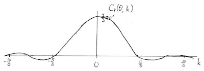
with Sf(θ, k) = 0 (Russ and I divide the Fourier transform into a cosine part C and a sine part S, see Eq. 11.57 in IPMB). Cf(θ, k) is a function of k, the wave number (also known as the spatial frequency). I won’t show all calculations; to gain the most from this post, fill in the missing steps. Cf(θ, k) is plotted below as a function of k.
A plot of the Fourier transform of the projection used in an analytical example of filtered back projection.

Step 1b: Filter

To filter, multiply Cf(θ, k) by |k|/2π (Eq. 12.39 in IPMB) to get the Fourier transform of the filtered projection Cg(θ, k)
The Fourier transform of the filtered projection used in an analytical example of filtered back projection.
with Sg(θ, k) = 0. The result is shown below. Notice that filtering removes the dc contribution at k = 0 and causes the function to fall off more slowly at large |k| (it's a high-pass filter).

A plot of the Fourier transform of the filtered projection used in an analytical example of filtered back projection.


Step 1c: Inverse Fourier transform

Next use Eq. 11.57 in IPMB to calculate the inverse Fourier transform of Cg(θ, k). Initially I didn’t think the required integral could be solved analytically. I even checked the best integral table in the world, with no luck. However, when I typed the integral into the WolframAlpha website, it gave me the answer
An integral from WolframAlpha.
The expression contains the cosine integral, Ci(z). After evaluating it at the integral’s end points, using limiting expressions for Ci(z) at small z, and expending much effort, I derived the filtered projection G(θ,x')
The filtered projection used in an analytical example of filtered back projection.
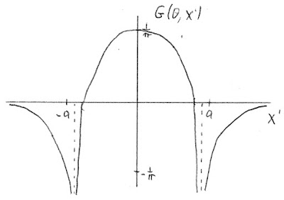
A plot of G(θ,x') is shown below.
A plot of the filtered projection used in an analytical example of filtered back projection.

Step 2: Back projection

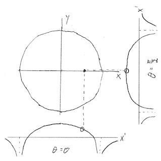
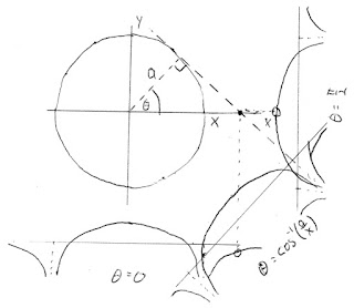
The back projection (Eq. 12.30 in IPMB) of G(θ,x') requires some care. Because f(x,y) does not depend on direction, you can evaluate the back projection along any radial line. I chose y = 0, which means the rotated coordinate x' = x cosθ + y sinθ in the back projection is simply x' = x cosθ. You must examine two cases.

Case 1: |x| less than a

In this case, integrate using only the section of G(θ,x') for |x'| less than a.

Instead of integrating from θ = 0 to π, use symmetry, multiply by two, and integrate from 0 to π/2.
At this point, I was sure I could not integrate such a complicated function analytically, but again WolframAlpha came to the rescue.

An integral from WolframAlpha.
(Beware: Wolfram assumes you integrate over x, so in the above screenshot x is my θ and b is my x.) The solution contains inverse hyperbolic tangent functions, but once you evaluate them at the end points you get a simple expression
The back projection obtained in an analytical example of filtered back projection.

Case 2: |x| greater than a

When |x| is greater than a, angles around θ = 0 use the section of G(θ,x') for |x'| greater than a and angles around θ = π/2 use the section for |x'| less than a.
The angle where you switch from one to the other is θ = cos-1(a/x). (To see why, analyze the right triangle in the above figure with side of length a and hypotenuse of length x.) The back projection integral becomes
If you evaluate this integral, you get zero.


Final Result

Putting all this together, and remembering that f(x,y) doesn’t depend on direction so you can replace x by the radial distance, you find
The filtered back projection.
We did it! We solved each step of filtered back projection analytically, and found f(x,y).

I’ll end with a few observations.
  1. Most clinical tomography devices use discrete data and computer computation. You rarely see the analysis done analytically. Yet, I think the analytical process builds insight. Plus, it’s fun.
  2. Want to check our result? Calculate the projection of f(x,y). You get the function F(θ,x') that we started with. To learn how to project, click here.
  3. Regular readers of this blog might remember that I analyzed this function in a previous post, where you can see what you get if you don’t filter before back projecting. 
  4. I have a newfound respect for WolframAlpha. It solved integrals analytically that I thought were hopeless. In addition, it’s online, free, and open to all.
  5. Most filtered back projection algorithms don’t filter using Fourier transforms. Instead, they use a convolution. I think Fourier analysis provides more insight, but that may be a matter of taste. 
  6. My bucket list includes finding an analytical example of filtered back projection when f(x,y) depends on direction. Wouldn’t that be cool! 
  7. Remember, there is another method for doing tomography: the Fourier method (see Section 12.4 in IPMB). Homework Problems 26 and 27 in Chapter 12 provide analytical examples of that technique.

Friday, March 9, 2018

Mechanics in Morphogenesis

Intermediate Physics for Medicine and Biology: Mechanics in Morphogenesis
Two weeks ago, I attended the Mechanics in Morphogenesis workshop sponsored by the Princeton Center for Theoretical Science. What was I doing at a workshop about morphogenesis? In the past few years, I have been dabbling in biomechanics (long story), with the goal of understanding mechanotransduction (how tissues grow and remodel in response to mechanical forces). My work might have applications to development, and I wanted to educate myself.

The meeting attracted a mix of experimental biologists and theoretical physicists. My two favorite talks were late Thursday afternoon (Feb 22). Ellen Kuhl of Stanford University discussed the “Mechanics of the Developing Brain,” focusing on how the brain folds into gyri and sulci. She said it was an appropriate topic for a talk at Princeton University because of Einstein’s brain (stolen during the autopsy by a Princeton Hospital pathologist). Kuhl discussed ideas from her article “A Mechanical Model Predicts Morphological Abnormalities in the Developing Human Brain” (Budday, Raybaud and Kuhl, Sci. Rep., Volume 4, Article Number 5644, 2014). This article appeared in Scientific Reports, an open access journal, so you can read the entire article online. The abstract appears below.
The developing human brain remains one of the few unsolved mysteries of science. Advancements in developmental biology, neuroscience, and medical imaging have brought us closer than ever to understand brain development in health and disease. However, the precise role of mechanics throughout this process remains underestimated and poorly understood. Here we show that mechanical stretch plays a crucial role in brain development. Using the nonlinear field theories of mechanics supplemented by the theory of finite growth, we model the human brain as a living system with a morphogenetically growing outer surface and a stretch-driven growing inner core. This approach seamlessly integrates the two popular but competing hypotheses for cortical folding: axonal tension and differential growth. We calibrate our model using magnetic resonance images from very preterm neonates. Our model predicts that deviations in cortical growth and thickness induce morphological abnormalities. Using the gyrification index, the ratio between the total and exposed surface area, we demonstrate that these abnormalities agree with the classical pathologies of lissencephaly and polymicrogyria. Understanding the mechanisms of cortical folding in the developing human brain has direct implications in the diagnostics and treatment of neurological disorders, including epilepsy, schizophrenia, and autism.
I also enjoyed a physics colloquium about “Motifs in Morphogenesis” by Lakshminarayanan Mahadevan of Harvard University. I liked how he presented simple, toy models that illustrate development (my type of physics). Mahadevan is a MacArthur “Genius Grant” Fellow, and I can see why. Great talk.

On Growth and Form, by D'Arcy Wentworth Thompson, superimposed on the cover of Intermediate Physics for Medicine and Biology.
On Growth and Form,
by D'Arcy Wentworth Thompson.
Mahadevan is also coeditor with Thomas Lecuit of a special issue published by the journal Development commemorating the groundbreaking book On Growth and Form. In their editorial (Volume 144, Pages 4197-4198, 2017) they write
Morphogenesis, the study of how forms arise in biology, has attracted scientists for aeons. A century ago, D'Arcy Wentworth Thompson crystallized this question in his opus On Growth and Form (Thompson, 1917) using a series of biological examples and geometric and physical analogies to ask how biological forms arise during development and across evolution. In light of the advances in molecular and cellular biology since then, a succinct modern view of the question states: how do genes encode geometry?...

On Growth and Form raised the question of the origin of biological shape in a physical framework. Since then, advances in our understanding of the biochemical basis of the laws of heredity have provided the modern conceptual understanding for how shapes develop anew at each generation, from a single cell – thus surviving the death of an individual through its offspring. As this Special Issue illustrates, we are now beginning to understand how genes encode geometry. As morphology both enables and constrains function, a natural next question is how biology creates functional (and plastic) shape that begins to link morphology to physiology and behaviour. As you mull this question, we would like to thank all the authors and referees of the articles in this Special Issue for their contributions, and we hope you enjoy reading it!
I had never been to Princeton University, so during lunch breaks I snuck out to look around the campus. It is beautiful (even in February), with many historical buildings. I particularly liked the gorgeous chapel, shown below.
 Princeton University Chapel
 Princeton University Chapel

Pyne Hall at Princeton University.
Pyne Hall


Alexander Hall at Princeton University
Alexander Hall


Joseph Henry electromagnet displayed in Jadwin Hall at Princeton University.
Joseph Henry electromagnet displayed in Jadwin Hall.

My poster with Debabrata Auddya, at the Mechanics in Morphogenesis workshop at Princeton University.
My poster with Debabrata Auddya.

My poster with graduate student Kharananda Sharma, at the Mechanics in Morphogenesis Workshop, at Princeton University.
My poster with graduate student Kharananda Sharma.

The Mechanics in Morphogenesis workshop highlighted how physics can be applied to biology and medicine, a topic central to Intermediate Physics for Medicine and Biology.

Friday, March 2, 2018

Chromatin Packing and Molecular Biology of the Cell

Molecular Biology of the Cell by Alberts et al.
Molecular Biology of the Cell,
by Bruce Alberts et al.
Intermediate Physics for Medicine and Biology: Chromatin Packing and Molecular Biology of the Cell In Section 16.9 of Intermediate Physics for Medicine and Biology, Russ Hobbie and I write
Cellular DNA is organized into chromosomes.… Figure 16.30 shows, at different magnifications, a strand of DNA, various intermediate structures that we will not discuss, and a chromosome as seen during the M phase of the cell cycle. The size goes from 2 nm for the DNA double helix to 1400 nm for the chromosome.
Figure 16.30 in IPMB is an illustration from the book Molecular Biology of the Cell by Bruce Alberts and his coauthors. This acclaimed textbook is currently in its 6th edition (2014). The Oakland University library has the 5th edition (2008), which I quote in this blog post.

A illustration showing chromatin packing, in Intermediate Physics for Medicine and Biology (left) and Molecular Biology of the Cell (right).
The black and white figure Russ and I include in IPMB has evolved into the beautiful color figure 4-72 in the 5th edition of the Molecular Biology of the Cell. Their caption reads
Figure 4-72 Chromatin packing. This model shows some of the many levels of chromatin packing postulated to give rise to the highly condensed mitotic chromosome.
Alberts et al. state at the start of their Chapter 4
In this chapter we begin by describing the structure of DNA. We see how, despite its chemical simplicity, the structure and chemical properties of DNA make it ideally suited as the raw material of genes. We then consider how the many proteins in chromosomes arrange and package this DNA. The packing has to be done in an orderly fashion so that the chromosomes can be replicated and apportioned correctly between the two daughter cells at each cell division. It must also allow access to chromosomal DNA for the enzymes that repair it when it is damaged and for the specialized proteins that direct the expression of its many genes. We shall also see how the packaging of DNA differs along the length of each chromosome in eucaryotes, and how it can store a valuable record of the cell’s developmental history.
One of the most interesting feature of this figure is the “beads-on-a-string” appearance of chromatin. Alberts et al. write
The proteins that bind to DNA to form eukaryotic chromosomes are traditionally divided into two general classes: the histones and the nonhistone chromosomal proteins. The complex of both classes of protein with the nuclear DNA of eukaryotic cells is known as chromatin. Histones are present in such enormous quantities in the cell (about 60 million molecules of each type per human cell) that their total mass in chromatin is about equal to that of the DNA.

Histones are responsible for the first and most basic level of chromosome packing, the nucleosome, a protein-DNA complex discovered in 1974. When interphase nuclei are broken open very gently and their contents examined under the electron microscope, most of the chromatin is in the form of a fiber with a diameter of about 30 nm (Figure 4-22A). If this chromatin is subjected to treatments that cause it to unfold partially, it can be seen under the electron microscope as a series of “beads on a string” (Figure 4-22B). The string is DNA, and each bead is a “nucleosome core particle” that consists of DNA wound around a protein core formed from histones.
For those who prefer videos over text and illustrations, below are two movies about how DNA is packaged in a cell.


I hope this post helps readers of IPMB understand better those “various intermediate structures that we will not discuss.” For more details, I recommend Molecular Biology of the Cell.